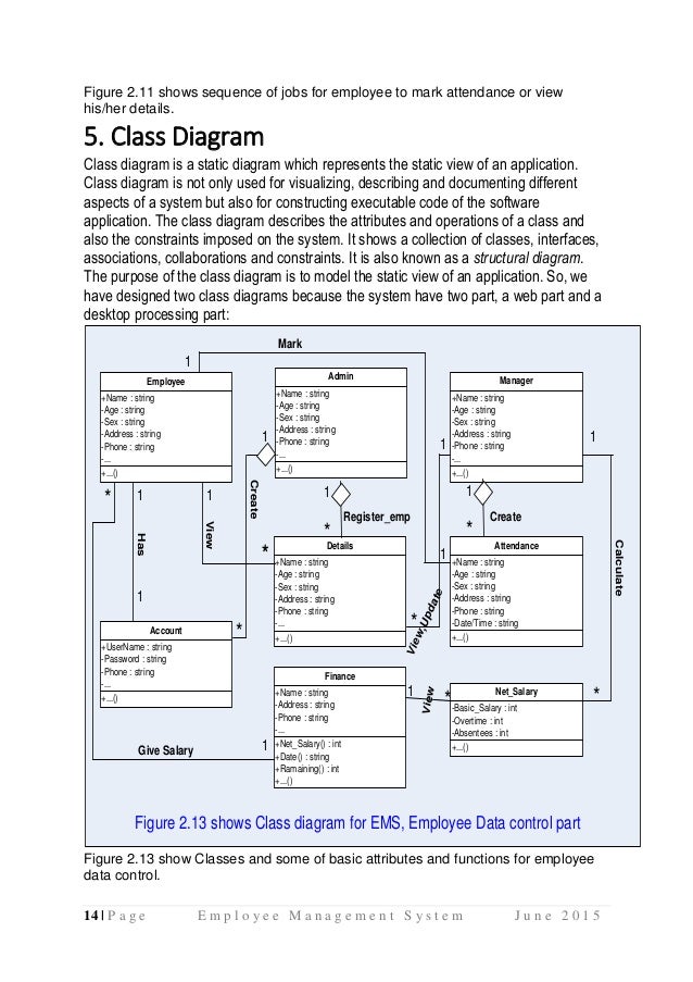
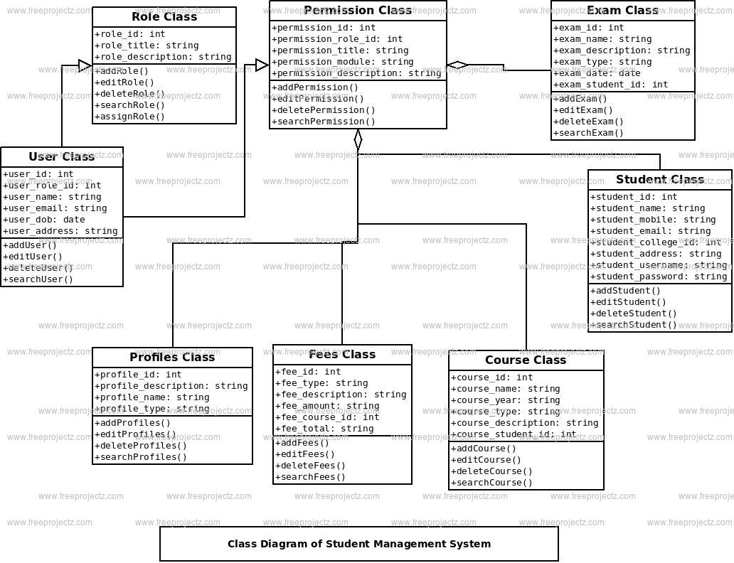
University Management System Class Diagram describes the structure of a University Management System classes, their attributes, operations (or methods), and the relationships among objects. The main classes of the University Management System are Colleges. Posted By freeproject on January 31, 2018. This is the UML sequence diagram of University Management System which shows the interaction between the objects of Student, Registration, College, Semester, Faculty. The instance of class objects involved in this UML Sequence Diagram of University Management System are as follows.
- UML diagram for University Information System. UNIVERSITY INFORMATION SYSTEM Date: 19th Nov 2014 AIM To develop a project University Information System using Rational Rose Software and to implement the software in Java. PROBLEM ANALYSIS AND PROJECT PLANNING A University Information System (SIS) is a software application for educational.
- May 04, 2018 Steps to draw the ArchiMate diagram example. Start Visual Paradigm with a new project; Create a new diagram by selecting Diagram New from the toolbar. In the New Diagram window, select ArchiMate Diagram and click Next. Enter Discharging Patients as diagram name and click OK to confirm diagram creation. This creates a blank ArchiMate Diagram.

- Draw Package Diagram For Students Management System
- Uml Student Management System Class Diagram
- Student Management System Class Diagram Uml
- UML Class Diagram Example for Transport System
- Stakeholder Management System | UML Class Diagram Example ...
- Draw A Usecase Class Diagram For Student Information System
- Draw Uml Class Diagram For Student Management System
- UML Class Diagram Example for Transport System
- Usecase Diagram For Student Information System
- UML Class Diagram Example for Transport System | UML Class ...
- Draw A Er Diagram For Student Management System
- Student Information System Of Use Case Class Diagram
- Statechart Diagram For Student Attendance Management System
- Chen Notation | Attendance Management System Class Diagram
- School Management System Class Diagram
- UML Class Diagram . Design Elements | UML Package Diagram ...
- UML Use Case Diagram Example Registration System | UML ...
- UML Use Case Diagram Example. Registration System
- Draw An Er Diagram For Student Information System
- Draw A Use Case And Class Diagram For Student Registration
- ERD | Entity Relationship Diagrams, ERD Software for Mac and Win
- Flowchart | Basic Flowchart Symbols and Meaning
- Flowchart | Flowchart Design - Symbols, Shapes, Stencils and Icons
- Flowchart | Flow Chart Symbols
- Electrical | Electrical Drawing - Wiring and Circuits Schematics
- Flowchart | Common Flowchart Symbols
- Flowchart | Common Flowchart Symbols

- Create a new project by selecting Project > New from the application toolbar. In the New Project window, enter Bus Route Management as project name and click Create Blank Project.
- To create an ERD, select Diagram > New from the toolbar. In the New Diagram window, select Entity Relationship Diagram and click Next. Enter Bus Route Management as diagram name and click OK.
- Let's start by creating the first entity Route. Select Entity in diagram toolbar and click on the diagram to create an entity. Name the entity Route and press Enter to confirm.
- Create columns in Route. Let's start with a primary key. Right-click on entity Route and select New Column from popup menu.
- Enter +id : varchar(10) and press Enter. Note that the + sign means that the column is a primary key. Varchar is the column type and 10 is the length.
- Enter fare : float and press Enter, then Esc to create another column.
- Create entity Stop. A bus route has many bus stops, while a stop can be shared by many routes. Therefore, there is a many-to-many relationship between Route and Stop. Place the mouse pointer over the Route entity. Drag out the Resource Catalog icon at top right.
- Release the mouse button and select Many-to-Many Relationship -> Entity from Resource Catalog.
Name the new entity Stop, You can see that a linked entity Route_Stop is automatically created in between Route and Stop, with foreign key added. - Create the following columns in Stop:
Key Name Type PK id int(10) name varchar(255) terminus blob
The diagram should now become: - A route has multiple bus schedules. Create an entity Schedule from Route with a one-to-many relationship. Move the mouse pointer to Route. Press and drag out the Resource Catalog icon. Select One-to-Many Relationship -> Entity to create entity Schedule.
- Create the following columns in Schedule:
Key Name Type PK id int(10) departure date arrive date - A schedule is handled by a bus. Create an entity Bus from Schedule, with an one-to-one relationship. Create the following columns in Bus:
Key Name Type PK vehicle_id int(10) fleet_id varchar(10) last_main date
The diagram should become: - A bus is driven by a bus driver. Create entity Driver from Bus with a one-to-one relationship. Add the following columns to Driver:
Key Name Type PK id int(10) name varchar(255) employ_date date
This is the final ERD.
Uml Structure Diagram


Uml Class Diagram Software
